DOWN4SOUND SUPER CHARGED BUNDLE - D4S JP40 & JP630 - 12V Lithium Car Audio Supercapacitor Battery ( 6000 - 12000W+ )
Down 4 SoundDOWN4SOUND JP40 + JP630 SUPERCHARGED BUNDLE - 12V Lithium Car audio Battery & Car audio Supercapacitor
Supercharge your audio system electrical with the JP40 and JP630 Bundle. Running both an ultracapacitor bank and a lithium battery in a car audio system can offer several benefits.
Here are a few:
- Improved power delivery: Ultracapacitors are ideal for handling sudden surges in power demand, while lithium batteries are better for providing a stable, consistent power supply. By using both together, you can create a more robust power system that is better equipped to handle the varying power needs of a car audio system.
- Longer lifespan: Both ultracapacitors and lithium batteries have long lifespans, but by using them together, you can extend the overall lifespan of the system even further. By offloading the sudden surges in power demand to the ultracapacitors, the lithium battery can operate more efficiently and last longer.
- Improved efficiency: Ultracapacitors can store and discharge energy very quickly, which means they can help to reduce the strain on the lithium battery and improve the overall efficiency of the system. By using both ultracapacitors and a lithium battery, you can create a power system that is more efficient and effective at handling the demands of a high-performance car audio system.
- Space savings: Both ultracapacitors and lithium batteries are smaller and lighter than traditional lead-acid batteries, which can help to save space in a car audio system. By using both together, you can create a more compact and streamlined system that takes up less space and is easier to install and maintain.
Overall, using both an ultracapacitor bank and a lithium battery can help to create a more efficient, effective, and reliable power system for a car audio system. However, it's important to choose the right components and ensure that they are installed and maintained properly to ensure maximum performance and lifespan.
Charging Voltage for Both the JP40 & JP630 : 14.8V MAX
JP630 - Car Audio Supercapacitor (Ultracapacitor) bank
The Down4sound JP630 ultracapacitor bank is an energy storage system that uses ultracapacitors (also known as supercapacitors) to store electrical energy. These devices have a higher energy density than traditional capacitors, but are still less dense than batteries.
The DOWN4SOUND JP63 is a specific model of ultracapacitor bank that is designed for use in car audio systems that looks like the Down4sound JP40 car audio lithium battery which resembles the Infamous down4sound amplifiers . It is intended to provide a quick burst of power to the car's amplifier, which can help to improve the overall sound quality of the system.
Benefits of the JP630 Car Audio Ultra Capacitor bank
JP 630 Ultracapacitors can be great for car audio electrical systems for a few reasons.
Firstly, The JP630 can provide a quick burst of power that can help to improve the overall sound quality of the system. When a car audio system requires a sudden surge of power (for example, when the bass hits in a song), an ultracapacitor bank can provide that power more quickly and effectively than a traditional battery. This can help to reduce distortion and improve the clarity of the sound.
Additionally, our car audio specific supercapacitor have a longer lifespan than traditional lead-acid batteries and agm batteries, which are commonly used in car audio systems. They can also be charged and discharged more quickly than batteries, which can be useful in high-performance audio systems where power demands can fluctuate rapidly.
Finally, the compact in style, which can be an advantage in a car where space is at a premium. This is the perfect solution car audio supercapacitor needs in electrical and is a good option for car audio enthusiasts who want to maximize their power output without adding extra weight to their vehicle.
JP60 SAFETY AND INSTRUCTIONS:
PROPER CHARGING IS CRUCIAL!
Charge before initial use. Be sure to read the instruction sheet for full instructions. Proper charging is crucial to the life of your Down4Sound battery. It is very important that the temperature of the capacitor remains cool with respect to the charge voltage. DO NOT OVER-TIGHTEN ULTRACAPACITOR BANK TERMINALS! Whether using the automotive post adaptors, bolts or screws, the tightening torque should never exceed 6 ft-lbs max on any Down4Sound ultracapacitor bank!
SAFETY :
Never touch the power terminals as any residual voltage can cause fatal electrical shocks. Always check with a calibrated meter that the ultracapcitor bank is discharged prior to handling the ultracapcitor bank, please see the step by step instructions in this manual for the discharge procedure.
1 - Carefully observe the polarity each time you connect to it,DO NOT REVERSE POLARITY.
2 - Prior to installation or removal, the ultracapcitor bank must be properly discharged.
3 - Provide sufficient electrical isolation for operation above 50VDC (relative to ground).
4 - Protect surrounding electrical and conductive components from incidental contact.
5 - Do not operate above specified voltage or temperature range.
6 - Do not touch terminals while charged, serious burns, shock or material fusing may occur.
UNPACKING
Please inspect the shipping carton for signs of damage prior to unpacking the carton. Report any damage to the carton, or the contents, to the carrier immediately. Retain all shipping materials until the ultracapcitor bank is fully inspected and determined to be operational. Do not use the terminals to lift the ultracapcitor bank out of the package. If any parts are determined to be missing or defective, an RGA number must be issued prior to returning the unit for repair or replacement. Please contact Down4Sound to request an RGA number.
HANDLING
Ultracapacitor banks are designed for years of maintenance free operation if handled, installed and used properly. These handling precautions should be observed.
1 - The only tools to be used on the ultracapcitor bank should be properly sized wrenches for the terminal and mounting bolts (hammers, chisels, files or power tools in general should not be used).
2 - Do not drop ultracapcitor bank invisible internal damage may occur. Use protective terminal caps while transporting the ultracapcitor bank or ensure that the ultracapcitor bank has been properly discharged before transporting.
INSTALLATION
Ultracapacitor bank can be mounted in any orientation and are qualified for shock and vibration. In addition, it is best to avoid mounting on or near significant heat sources such as engine exhausts or solar heated panels.
STORAGE
The ultracapacitor bank can be stored in the original package discharged in a dry place. Observe the maximum storage temperature as stated in the specifications. Discharge used ultracapacitor bank prior to stock or shipment. TEMPERATURE RANGE
Range, Operating Temperature: -40F / 149F (-40oC / 65C))
Range, Storage Temperature: -40F / 158oF (-40C / 70C) DISPOSAL
Always recycle according to local codes and regulations for flammable materials.
ENVIRONMENTAL
For best results ultracapacitor bank should not be exposed directly to the environment, particularly the avoidance of direct splashes should be considered. In systems with voltages greater than 60V it is highly recommended to use protective terminal caps. Ultracapacitor banks that are expected to see significant cycling should be mounted in free air or in a forced ventilation housing. Care should be taken to protect ultracapacitor banks in potentially corrosive environments and direct water splash or spray should be avoided. In all environments, the best possible performance is aided by using an anti-oxidation agent for all terminal connections. Careful design consideration should be given to the application to prevent the overheating of the ultracapacitor bank. Please refer to the operational temperature range on the data sheet and be sure to allow for internal heating of the ultracapacitor bank. If you require help with the design considerations and sizing please contact Down4Sound for assistance.
ELECTRICAL
Ultracapacitor bank can be mounted in series and/or parallel with each other. Care should be taken to insure that similar capacitance is used for series chains and that if different type or age ultracapacitor bank are used in parallel configurations the differences in ESR are accounted for in your design. Appropriate size bus bars or cables and terminals should be used for the application. Please note, that to minimize system loses, the capacitors do not have fusing or internal circuit breakers, careful consideration in the system design should be taken to prevent over current. With the low ESR of the capacitors they can deliver very large amounts of current. The worst-case fault current should be considered when sizing the wire for this application. Thread locking should be done with star washers or an appropriate chemical thread locker applied to the threaded portions only. Care should be taken in cable routing to not impose undue forces(torques or tensions) on the ultracapacitor bank terminals. Only appropriately sized ring terminals or bus bars for the expected currents should be used.
OPERATION
All Supercapacitor / rultracapacitor banks should only be operated within their prescribed voltage, constant current and temperature, operating window. NOTE: Operation of above 149F/65C will void the warranty.
MAINTENANCE
The car Audio supercapacitor /ultracapacitor bank should be kept free of dust and debris and cleaned at a regular interval. In inside locations, that should be no more than annually however this may vary with your particular circumstances. Outside location will be as needed. Once the ultracapacitor bank is discharged, proceed with cleaning with a cloth and a simple water/soap solution. Avoid the use of hoses or pressurized sprays. Once the assembly is clean check for properly torqued fasteners and note any damage to any of the housings or signs of internal damage and replace as necessary. In high vibration applications, fasteners used for mounting as well as electrical connections should be checked for torque every 6 months. DISCHARGING
Before replacing or disconnecting an ultracapacitor bank or individual capacitors they should be properly discharged to limit the risk of dangerous electrical shocks and sparks. Even a properly discharged ultracapacitor bank can naturally rebound in certain conditions. The provided lamp can be used to safely discharge the ultracapacitor bank by connecting one lead to the positive side of the ultracapacitor bank and the other lead to the negative side. After the lamp has dimmed out and cooled then it is safe to disconnect and remove from the system. The lamp can be removed and a shorting wire can be connected between the terminals of the ultracapaci-tor bank to prevent it from building up a charge. This should especially be done if the ultracapacitor bank will be sitting unused for an extended period of time.
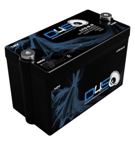
JP40 12 Volt Lithium Car audio Battery
The perfect solution to 12v car audio lithium battery wonders is here! This will help out those who both do and dont have a high amperage custom alternator. NOTE that having an upgraded electrical with a high output alternator will benefit the JP 40 - 12v car audio lithium battery but is not needed. This 12v car audio lithium battery is good between 6000w thru 12,000w systems.
Wattage rating varies widely depending on alternator input ( 6000-12000W)
USE ONLY INSIDE OF VEHICLE. (Do not use under the hood or outside of vehicle. DO NOT use with any other type of batteries including different lithium chemistries and any lead acid or AGM batteries)
Example:
- 120-160A alternator - 6,000w rating
- 240-270A alternator - 8,000w rating
- 320-370A alternator - 10,000w rating
- Single 450A Alternator Or Dual 240+a alternators - 12,000w rating
This battery is a Lithium Iron Phosphate (LiFeP04/LFP). Down4sound's JP40 is the most powerful LFP for its size in the car audio industry.
- JP40 Battery Size is 10.5 inches long, 8.25 inches wide, and 3 inches tall. Weighing in at 14 pounds.
- The JP40 is the first car audio lithium battery with an integrated voltage and temperature monitoring and notification system. We are taking the guesswork out of the picture.
- The JP40 also features a compact LOW profile & infinitely expandable car audio lithium battery. The JP40 shares a similar look to JP Amplifiers with its Sleek machined aluminum housing, allowing rapid heat dissipation; a bonus is that's it is easily mountable.
No voltage boosting necessary- DO NOT EXCEED 14.8v as this will cause damage to the battery.
- Onboard balancing
Aluminum housing isolated from ground to reduce the risk of short if 12V power accidentally contacts the battery housing.
SPECIAL INSTRUCTIONS FOR THIS PRODUCT
This product has a metal housing. The metal housing is used to wick away the heat generated by the
lithium cells under high load to keep them cooler and so they can operate at higher efficiency. Metal also
conducts electricity and requires added safety considerations when using this product. This battery is
intended to be properly mounted before use. If the battery is not mounted it is possible for the battery to
shift during use and it could come into contact with metal causing a short to the battery. Extra care must
be taken when attaching ring terminals, bus bars, and other attachment. The insulated area around the
terminals and the safety bar between the terminals make accidental shorts much less likely to occur.
Make sure all wires and connections in the vicinity of the battery are properly insulated to avoid any
accidental shorts.
PROPER CHARGING IS CRUCIAL!
Charge before initial use, be sure to read the instruction sheet for full instructions. Proper charging is
crucial to the life of your Down4Sound battery. It is very important that the temperature of the battery
remains cool with respect to the charge voltage.
DO NOT OVER-TIGHTEN BATTERY TERMINALS!
Whether using the terminal adapters, bolts or screws, the tightening torque should never exceed 6 ft-lbs
max on any Down4Sound battery!
INTRODUCTION
Your new Down4Sound lithium battery is the industry leading lithium battery made for pulse discharge
loads. Lithium cells hold, in general terms, three times the energy density of lead acid batteries. However
they need careful management to be safe and provide a long service life. Fundamentally, they have
serious risks associated with them and these must be understood to avoid danger, loss of property, and
personal injury. Don’t let the size of this battery fool you, it is very powerful, and if not operated correctly,
capable of being very dangerous.
TECHNICAL ASSISTANCE
Be sure to check out down4soundshop.com for additional technical and product information.
INSTALLATION
You may mount the lithium battery in any direction as long as it is secured from short circuits and/or
movement. One word of caution though. This battery is very light and therefore it does not require a great
deal of force to hold it. Do not crush the battery with battery retention systems. The threads are M6-1.0.
Optional terminals are available. Be extremely careful when making connections. Remember there is no
low voltage disconnect, reverse polarity, or short circuit protection on the main terminals of this battery.
Further the power output of a lithium battery is four times that of typical lead acid batteries. Short circuits
will flow huge amounts of current instantly with the ability to melt metal.
Do not expose to temperatures above 60oC (140oF). Avoid mounting this battery in the engine
compartment if at all possible. Elevated temperatures accelerate the aging process of most battery types
and lithium batteries are especially sensitive to high temperatures. Open circuit voltage should be above
12V, when fully charged after resting for 8 hours. If it is less than this after resting for 8 hours, the battery
should be taken out of service and must be checked for capacity, cell balance, and State of Health before
resuming operation.
WARNINGS
To reduce the risk of fire or personal injury including burns:
- Do not over charge the battery (meaning exceed the maximum voltage OR amperage and remove the
charger once the battery is at 100% SOC.).
- Do not short circuit the terminals.
Use with alternators requires that the charging voltage be limited to 14.4V or less. 13.8~14.0 is
preferred for 12V models.
- Do not charge this battery with an alternator if the terminal voltage is below 10V.
- Contact Down4Sound for assistance before proceeding.
- Avoid high temperature. Never operate the battery in environments above 140o
F or if the battery itself
exceeds 140o F at any point. WARNINGS(cont’d)
- Lithium batteries contain flammable gases. Have a plan in place to respond to possible fire.
- Disconnect the battery in total before welding anywhere on the vehicle. Do not submerse in water. This
battery is not waterproof.
- Do not crush, puncture, or dispose in fire or water.
- Do not attempt to open, disassemble, or service the battery pack.
BATTERY MONITORING FUNCTIONS
The remote provides real-time monitoring and display of battery voltage, percentage battery
capacity, and the internal temperature of the battery.
- Low voltage alarm: The voltage display will flash in real time when the voltage is getting close
to fully discharged. Charge battery before the voltage drops below 10V. Do not discharge the
battery lower than 10V or damage may occur.
- High voltage alarm: The voltage display will flash as the battery is close to the maximum
charge. Do not allow the battery to over charge or damage may occur.
Low temperature alarm:
- The temperature display will flash if the battery temperature drops
below -20 C / -4 F. If the battery temperature is at or near this threshold it can be charged
with low voltage is
approaching 55 C / 149 F. If the battery temperature is near or at this threshold, discontinue
use of the battery until the temperature drops to the operational range. Over"__mce_add_custom__" title="JP40 Lithium Battery remote " src="https://cdn11.bigcommerce.com/s-209k8v1/product_images/uploaded_images/screen-shot-2022-03-21-at-8.24.15-pm.png" alt="JP40 Lithium Battery remote " width="738" height="644" />
THE IMPORTANCE OF THE REMOTE DISPLAY:
In demanding conditions of high amperage discharge, fast charging, and extended high
amperage discharge, it is important to monitor the battery to keep the battery from being
damaged. If the battery is discharged below the minimum voltage the battery will be damaged,
and such damage will cause the battery to lose performance and/or cause a dangerous
operating condition which could result in personal injury, equipment damage, or death. The
same is true if the battery is allowed to over heat, or be over charged. This remote tool is a way
to monitor the battery’s operation within the specified parameters without a putting restrictive
Battery Management System (BMS) that reduces the amount of control the user has over the
battery’s operation. As with all tools, it is only as effective as the user. If the warnings are not
heeded, or ignored the battery may become damaged, and this will void the warranty.
CONNECTION METHOD
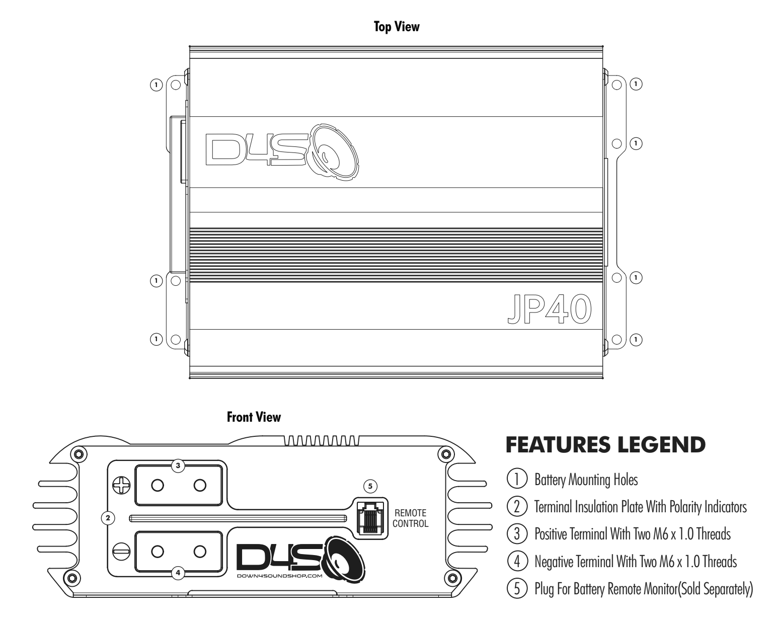
The remote monitor has 2 plugs, a Phone jack, and an 2 pin port. The phone jack is connected
from the remote monitor and the plug labeled “remote” on the face of the battery.
The 2 pin plug on the remote monitor can be used to connect the monitor to a 12V power
supply, (Example: the cars ignition system.) as a alternate power supply to keep the remote
monitor from using the battery’s power.
INSTRUCTION FOR USE:
Connect the battery with the remote monitor using the supplied cable.
To Change Voltage/Capacity Display
The default mode of the voltage/capacity display is the battery’s voltage. If the button
marked “Voltage/Capacity” is pressed, the display will change to the show the battery’s
capacity in percentage of remaining charge. If the button is pressed again, it will return to
the default display.
To Change The Temperature Display:
The default mode of the temperature display is in Fahrenheit (Fo). If the button marked
“Temperature” is pressed, the display will change to the unit of Celsius (Co). If the button is
pressed again, it will return to the default display.
REMOTE
The JP40 Remote Display ships in the default setting that allows for plug and play use with the
JP40 battery. Initial programming is not required when you purchase this remote for use with
JP40. However, this remote is also designed to be used universally with AGM, Li-Po, LTO and
other LFP type batteries in many configurations. Although the programming details shown
below are accessible, they are only applicable to the universal remote model, which includes
the voltage and temperature sending unit that can be used external to any battery. This will
not allow for the accurate internal temperature readings you get from your JP40 Battery since
the sending unit is already inside the battery. The programming instructions are provided
below for knowledge about these functions in case the menu is accessed accidentally, and the
settings need to be corrected for accurate functionality of the remote display.
Press and hold the “Menu” button for six (6) seconds to access the program mode. The display
will flash indicating it is in program mode. If no buttons are pressed within six (6) seconds the
unit will automatically exit program mode.
To set battery type, enter program mode. Use the Buttons marked with the up and down arrows
to select the correct battery type. The battery types available to select are as follows:
L - Lithium Ion Batteries (Li-ion, Li-po) [ Cell Voltage is 3.6V-3.8V ]
F - Lithium Iron Phosphate Batteries (LFP) [ Cell Voltage is 3.2V ]
P - Lead Acid Batteries (AGM) [ Battery Voltage is 12V ]
t - Lithium Titanate Oxide Batteries (LTO) [ Cell Voltage 2.4V ]
Once the battery type is selected, press the “Menu” button again to set the number of cells in
series. The display will once again flash,
Set the number of cells in series using the up and down arrows as before.
EXAMPLE: 3S - is set to 03
4S - is set to 04
5S - is set to 05.... Etc.
After six (6) seconds with no buttons pushed, the unit will exit program mode automatically. If
the setting are not correct, re-enter program mode and select the correct settings. If the remote
setting are incorrect, the information displayed by the remote will also be incorrect.
THE EFFECTIVE RANGE BY TYPE OF BATTERY
The limits for the number of cells or batteries in series are noted below:
Lithium Ion ( Li-ion, Li-po ) (L) - L02 - L20
Lithium Ion Phosphate (LFP) (F) -F03 - F24
Lead Acid Batteries (AGM) (P) - P01 - P06
Lithium Titanate Oxide Batteries (LTO) - T05 -T24
UBK INSTRUCTIONS
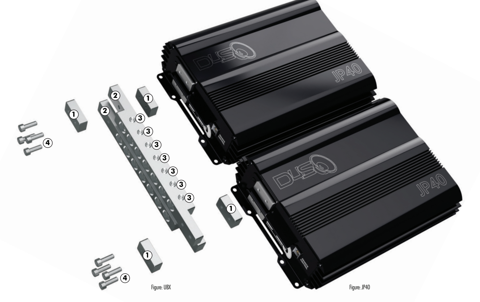
The “Universal Bus Kit” is used to connect in parallel two (2) or more batteries. By adding
additional kits more batteries can be added to the circuit. The bas bars also serve as terminal
blocks with seven (7) 0 Gauge or 00 Gauge positive and negative connection ports on each pair
of bus bars.
The “Universal Bus Kit” contains two (2) major components, the bus bars and bus bar spacers.
The spacers are used to fill the space at the ends of the bus bars if only one bar is used. If more
than one bus bar is used to connect three or more batteries, the spacers will always be on the
outer most ends of the bus bars.
FEATURES LEGEND
1 Spacers, total of four (4) per kit, two per bus bar.
2 Bus bars, total of two (2) bus bars per kit.
3 Set screws, total of fourteen (14) per kit, seven (7) per bus bar.
4 Long mounting screws, eight (8) per kit, four (4) per bus bar.


